Three-Axis Antenna Testing Simulation Turntable
FEATURES
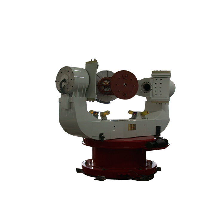
The Three – Axis Antenna Test Simulation Turntable is composed of two main parts: the mechanical table body and the measurement and control system. The table body adopts the U – U – T structure, a precision mechanical shaft system, and a high – rigidity structure. It mainly has functions such as simulation, position, and rate. It can simulate the three – dimensional movement of a carrier. It is used in ground hardware – in – the – loop simulation systems, providing a near – real movement environment for loads such as radar antennas. It can also provide single – axis, dual – axis, or three – axis positioning and rate references for the measured load, and is used for the testing and experimentation of the load.
PARAMETER TABLE
| Model | LRT – 1 | ||
| Function | Three – axis rate, position | ||
| Description | Standard | Custom | |
| Maximum Load(Kg) | 150 | 5 – 500 | |
| Load Dimensions(mm) | Φ750×500 | Custom | |
| Inner Axis |
Minimum Rate (°/s) | ±0.001 | ±0.0001 – ±0.01 |
| Maximum Rate (°/s) | ±400 | ±50 – ±10000 | |
| Rate Accuracy and Stability (360° average) | 1×10⁻⁴ | 1×10⁻⁶ – 1×10⁻³ | |
| Highest Position Accuracy (″) | ±5 | ±1 – ±30 | |
| Maximum Angular Acceleration (°/s²) | 800 | 10 – 10000 | |
| Maximum System Bandwidth (Hz) | 4 | 5 – 15 | |
| Middle Axis |
Minimum Rate (°/s) | ±0.01 | ±0.0001 – ±0.01 |
| Maximum Rate (°/s) | ±260 | ±50 – ±1200 | |
| Rate Accuracy and Stability (360° average) | 1×10⁻⁴ | 1×10⁻⁶ – 1×10⁻³ | |
| Highest Position Accuracy (″) | ±5 | ±1 – ±30 | |
| Maximum Angular Acceleration (°/s²) | 400 | 10 – 5000 | |
| Maximum System Bandwidth (Hz) | 3 | 2月12日 | |
| Middle Axis |
Minimum Rate (°/s) | ±0.01 | ±0.0001 – ±0.01 |
| Maximum Rate (°/s) | ±260 | ±50 – ±1000 | |
| Rate Accuracy and Stability (360° average) | 1×10⁻⁴ | 1×10⁻⁶ – 1×10⁻³ | |
| Highest Position Accuracy (″) | ±5 | ±1 – ±30 | |
| Maximum Angular Acceleration (°/s²) | 200 | 10 – 5000 | |
| Maximum System Bandwidth (Hz) | 3 | 2 – 10 | |
| Slip Ring(Rings) | / | / | |
| Turntable Weight(Kg) | 7000 | / | |
| Overall Dimensions(mm) | Φ2580×5000 | / | |